Ruregold propone due nuovi strumenti per progettare con i sistemi FRCM, costituiti da materiali compositi in fibra di PBO e Carbonio in combinazione alle malte tecniche cementizie: i Software di Calcolo Ruregold per il dimensionamento e la verifica del rinforzo strutturale di elementi in calcestruzzo e muratura.
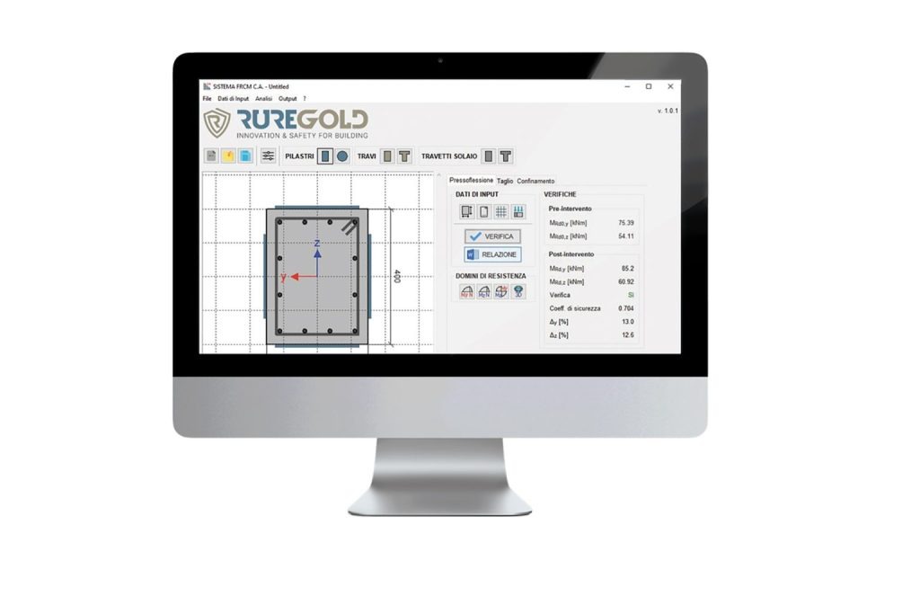
Due le versioni disponibili:
Sistema FRCM C.A., dedicato al rinforzo di elementi in calcestruzzo armato quali pilastri, travi e travetti di solaio, consente la verifica:
di pilastri a sezione rettangolare o circolare, piena oppure cava, per pressoflessione deviata, taglio deviato e confinamento,
di travi a sezione rettangolare o a T per flessione e tagli
a flessione di travetti di solaio a sezione rettangolare o a T.
Sistema FRCM Muratura, dedicato al rinforzo di elementi in muratura come pannelli, pilastri e colonne, consente la la verifica:
su pannelli per azioni nel piano (taglio e pressoflessione) e azioni fuori piano,
su pilastri e colonne per pressoflessione e confinamento e il presidio per la messa in sicurezza delle tamponature esterne.
Esempi di calcolo
Rinforzo trave in C.A. a flessione
Il software di calcolo implementa le formulazioni analitiche presenti all’interno del CNR-DT 215/2018 (§5.1 per gli elementi in c.a.), permettendo all’utente di definire solo le caratteristiche geometriche e meccaniche dell’elemento in c.a. e le sollecitazioni agenti per effettuare le verifiche di resistenza.L’interfaccia grafica inoltre consente al progettista di visualizzare la sezione dell’elemento modellata. Di seguito si riportano i principali step da seguire per effettuare la verifica della trave, descritte in figura 1 e 2.
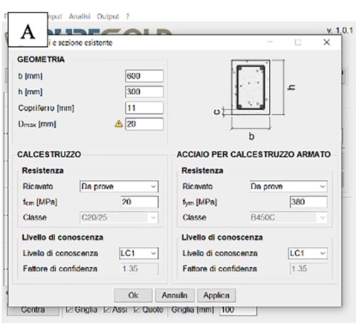
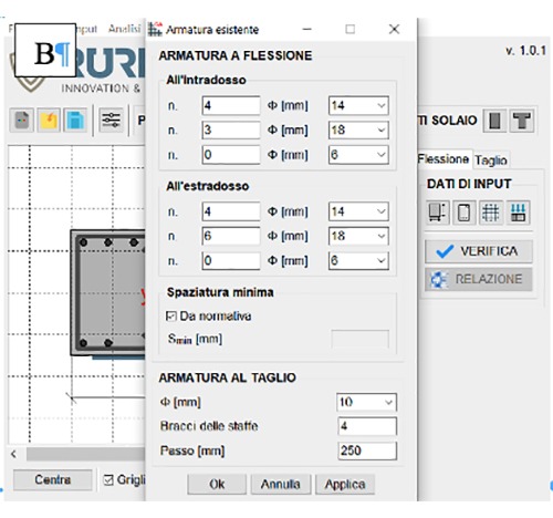
Figura 1 A) definizione della geometria della sezione e della resistenza dei materiali;
Figura 1 B) definizione delle armature longitudinali e trasversali dell’elemento
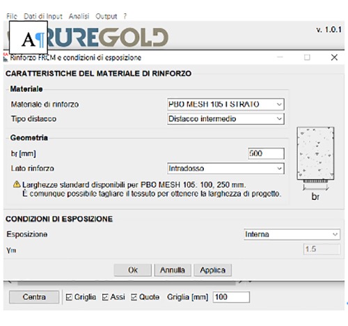
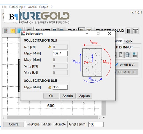
Figura 2 A) definizione della tipologia di rinforzo;
Figura 2 B) inserimento delle sollecitazioni agenti per le verifiche sezionali
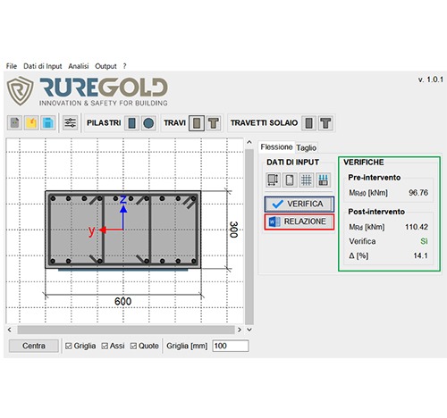
Terminata la fase di input dei dati e della definizione del rinforzo da applicare, è possibile effettuare la verifica di resistenza richiesta. In automatico si apre una colonna che riporta i valori resistenti pre-intervento e post-intervento, la percentuale di incremento raggiunta e la verifica di resistenza, come mostrato in figura 3.
Conclusa la fase di analisi, sarà possibile infine generare una relazione di calcolo contenente il riepilogo dei dati di progetto, l’elenco delle normative di riferimento e una descrizione schematica dell’applicazione del sistema di rinforzo.
Figura 3) Schermata del software a seguito della verifica e generazione della relazione di calcolo
Rinforzo pannello murario a pressoflessione nel piano
Il software di calcolo implementa le formulazioni analitiche presenti all’interno del CNR-DT 215/2018 (§4.1 e §12 Appendice 1), permettendo all’utente di definire solo le caratteristiche geometriche e meccaniche dell’elemento in muratura e le sollecitazioni agenti e il rinforzo da applicare per effettuare le verifiche di resistenza.
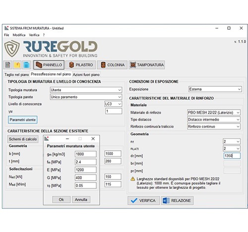
Di seguito si riportano i principali step, appena descritti, per effettuare la verifica del pannello (figura 4).
Figura 4) Definizione della geometria della sezione, della resistenza dei materiali (anche attraverso il comando “Parametri Utente)” e del rinforzo che si intende applicare).
Terminata la fase di input dei dati, è possibile effettuare la verifica di resistenza richiesta. In automatico si aprirà una colonna che riporta i valori resistenti pre-intervento e post-intervento, la percentuale di incremento raggiunta, la verifica di resistenza e la necessità, o meno, di adottare opportuni connettori, come mostrato in figura 5.
Figura 5) Schermata del software a seguito della verifica.
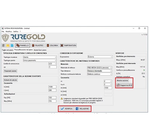
Anche in questo caso, una volta conclusa la fase di analisi, sarà possibile visualizzare schematicamente la sezione dell’elemento, il diagramma di interazione M-N (figura 6) e generare una relazione di calcolo contenente il riepilogo dei dati di progetto, l’elenco delle normative di riferimento e una descrizione schematica dell’applicazione del sistema di rinforzo.
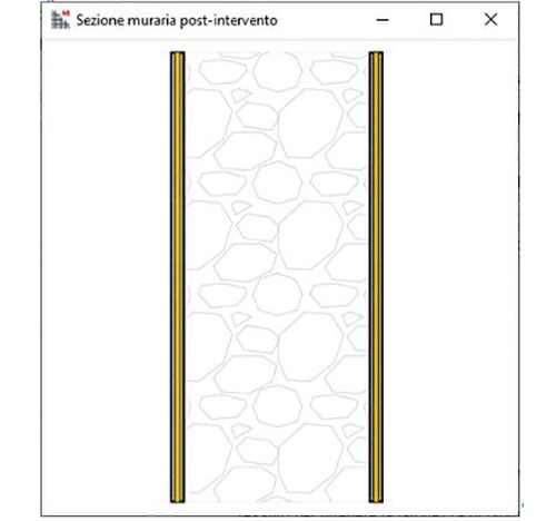
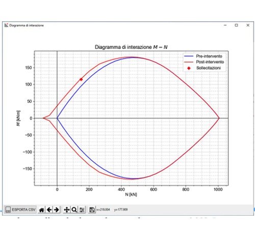
Figura 6) Schematizzazione del rinforzo sul pannello e il relativo dominio di interazione M-N.


